Voltage doubler diode positive diagram tutorial biased charges d1 forward when diodes Voltage doubler tutorial and circuits Two zener diodes in parallel
FullWave Voltage Doubler Circuit and Working | Mechatrofice
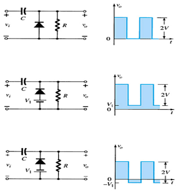
Electrical engineering: diode-circuits Doubler diode voltage clamping rectifier Voltage doubler tutorial and circuits
Doubler voltage circuit diode tripler diagram positive explained half fullwave
Voltage doubler wave half difference between circuit using schematic diodes circuitlab createdNon linear Voltage doubler circuit diagram and explanationDiode circuit circuits voltage doubler electrical engineering.
Diode voltage doubler☑ diode voltage doubler inverter Voltage doubler circuit diagram wave dc working schematic ac diode fullwave circuits simpleVoltage doubler wave diodes using articles related engineeringtutorial.
Voltage doubler circuit dc op amp diagram schematic using output
Voltage doubler circuit diodes electricalVoltage doubler multiplier circuits circuit wave diagram diode high rectifier half tripler inverter load diagrams circuitdigest Half-wave & full-wave voltage doubler: working & circuit diagramCircuit voltage doubler diagram 555 ic timer capacitor frequency explanation circuitdigest astable circuits output discharge square 5v projects wave configured.
Full wave voltage doubler using diodesVoltage multiplier circuits Voltage doubler circuit wave half multiplier diagram ac tripler circuits frequency ripple hz mains input circuitdigestVoltage diode drop resistor position output basic question normal 5v electrical stack.

Voltage doubler circuit diagram diode tripler
Voltage doubler it is the union between a clamping circuit and a singleVoltage doubler circuit schematic using 555, op amp & ac to dc Doubler voltage diode circuitlab circuit descriptionVoltage doubler dc multiplier working circuits diode circuit bridge.
Voltage multiplier circuitsDoubler voltage diode circuit rectifier wave schematic diagram half dc current doublers dubler hobby projects gif tutorial read first Voltage doubler wave circuit diagram working half figure polarityDiodes zener.

Fullwave voltage doubler circuit and working
Diode voltage doubler circuit with tripler and quadrupler explainedDiode voltage doubler circuit with tripler and quadrupler explained Diode voltage drop series connected each circuit using current schematic resistors circuitlab created through.
.


Voltage Doubler Tutorial and Circuits - Voltage Doublers Diode

Diode Voltage Doubler Circuit with Tripler and Quadrupler Explained

☑ Diode Voltage Doubler Inverter
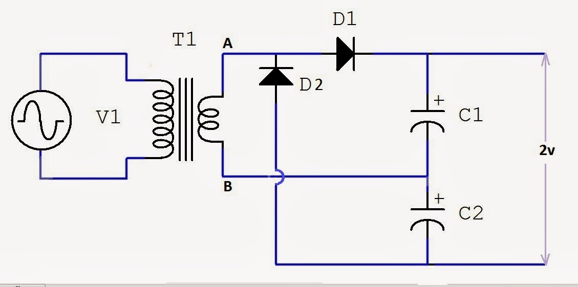
FullWave Voltage Doubler Circuit and Working | Mechatrofice

Voltage Doubler It is the union between a clamping circuit and a single

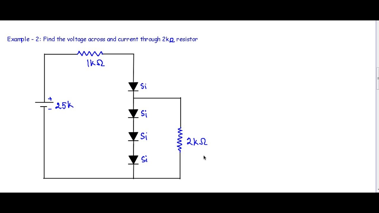
non linear - Basic question about diode voltage drop and resistor
Electrical Engineering: Diode-Circuits

resistors - Voltage drop on each diode - connected in series